In these few steps you will be able to terminate your cable with RJ45 node
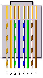
| Pin # | T568B | T568A |
| 1 | White/Orange | White/Green |
| 2 | Orange | Green |
| 3 | White/Green | White/Orange |
| 4 | Blue | Blue |
| 5 | White/Blue | White/Blue |
| 6 | Green | Orange |
| 7 | White/Brown | White/Brown |
| 8 | Brown | Brown |
Based on TIA/EIA-568-B.1-2001, the T568A and T568B wiring schemes define the pinout, or order of connections, for wires in eight-pin modular connector plugs and jacks.
The only difference between T568A and T568B is that pairs 2 and 3 (orange and green) are swapped. Both configurations wire the pins “straight through”, i.e., pins 1 through 8 on one end are connected to pins 1 through 8 on the other end, and the same sets of pins are paired in both configurations: pins 1 and 2 form a pair, as do 3 and 6, 4 and 5 and 7 and 8.
Step 1: Materials needed
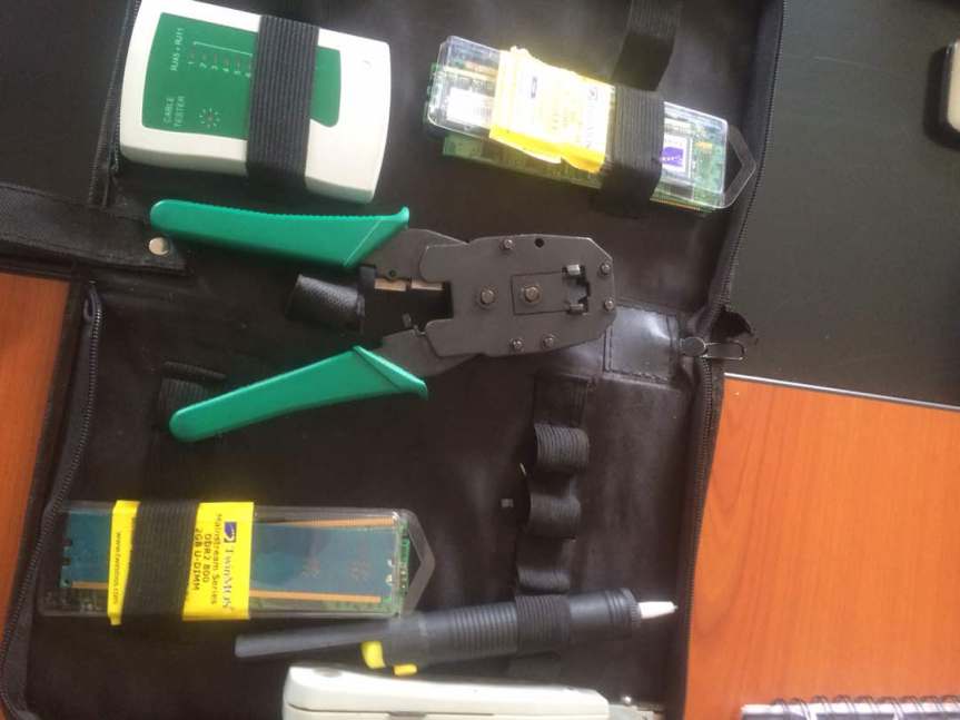
• Wire Strippers – I recommend the IDEAL Telecomm/Datacomm Wire Strippers
• Wire Cutters (Side Cutters will work)
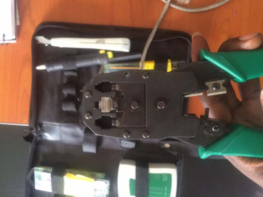
• RJ45 Crimping Tool
• Bulk CAT6 Network Cable
• Ruler
• 2 Wire Boots (Optional, not pictured)
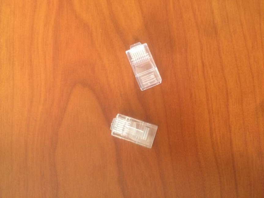
• 2 – RJ45 Modular Data Plug (Ends pictured below)
Step 2: Measure the Cable
Using the coil of wire, pull the necessary amount of wire for the connection you need to make. Be sure to include an extra 2 inches on either end of the wire for the data plug.NOTE: Network cables have a maximum length, depending on which type is being used. Although maximum length varies by manufacturer, a common rule of thumb is 650 feet for a CAT6 cable and 250 feet for a CAT5e cable. If the length of the wire between two powered network devices exceeds this length, signal degradation and data loss may occur.TIP: Do your best to run the wire along the path it will follow between the two devices. Do not pull the cable tight between two points and be sure the cable is not kinked or tightly pulled around corners. The cable should have a little wiggle room.TIP: If the location of the wire allows, consider including an extra length in the cable. This prevents having to make another cable if one device needs to move a short distance after the cable is made. One way of adding a short length to the cable is to wrap it around a closed fist 2 or 3 times.
Step 3: Strip the Cable
Measure out 1.5 inches from one end of the wire and place the wire in the wire strippers at that location. The cable should be snug in the strippers, but not tight. For the recommended strippers, the second notch inward is appropriate.Step 2:
Ensure the blade of the wire stripper is perpendicular to the wire and turn the wire stripper around the cable once, which will score the sheathing of the wire.NOTE: Turn the wire stripper only once. Turning the stripper more than once increases the chance of cutting the sheathing of the inner wires. If the inner sheathing is cut, it can make the next steps more difficult or cause the wires to break.Step 3:
Remove the wire stripper and gently bend the cable along the score line. This should break the sheathing which can be pulled off the wire and thrown away.NOTE: Some wires contain a strand of fiber similar to the one shown in the image. Cut the fiber from the cable near the end of sheathing.NOTE: As you become more experienced with making Ethernet cables, you may not need to remove the full 1.5 inches of sheathing.
After the sheathing is removed, the bundle of 8 wires will be exposed
Step 4: Prepare Wires
Step 1:
Separate the twisted pairs into an “x” pattern as shown. When you look down the cable from the end, you should not see any of the twisted pairs crossing over each other. Also, the wires do not have to be in the same configuration as seen in the image as long as the wires are not crossing over each other.
Step 2:
Separate the wires of the twisted pairs. When the wires are separated, they should not cross over each other.
Step 3:
Assemble the wires into a fan shape and organize for the data plug. There are two common ways to organize the wires for the data plug. Regardless of which one you use, both ends of the cable MUST use the same configuration otherwise the cable will not work.
I use the following configuration moving left to right (Clockwise from the 9 o’clock position)
• Orange-White
• Orange
• Green-White
• Blue
• Blue-White
• Green
• Brown-White
• Brown
TIP: If this is the second end of the wire, look at the end that is already terminated to ensure the cables are the same on both ends. If you made a mistake on your first end, this is your opportunity to fix it by configuring your wires the same way as the terminated end.
NOTE: The wire configuration used above is the T-568B configuration, which is the most common configuration. The T-568A configuration works just as well and will not affect the transmission quality of the cable. Both of these configurations use the design of the wires (twisted pairs) to insulate the wires from each other and prevent interference and data loss. It is useful to memorize whichever configuration you prefer. If you are interested in making an Ethernet Crossover cable, just do an image search for “Ethernet Crossover Cable Diagram” to get a wire configuration diagram.
Step 4:
Firmly grasp all the wires near the sheathing and slide your fingers up, collecting all the wires into a flat line. Make sure none of the wires jump positions. When looking at the wire colors from left to right, the wires should be in the same configuration as described above.
Step 5:
Straighten the wires. The wires do not have to be even, just straighten them as best you can.
TIP: If you have a table with a sharp (not rounded) edge, pinch the cable between your thumb and the edge of the table. Next, pull the wires between your thumb and the edge. This will straighten the wires and make them easier to manipulate for the next steps.
Step 6:
Using the wire cutters, trim the tips of the wires so all of the wires are even. Make sure the cut is perpendicular to the wires.
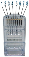
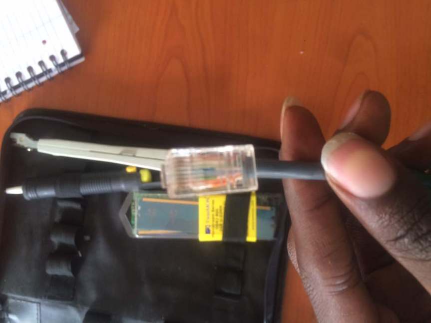
Insert the wires as shown into your RJ45
Step 6: Terminate the Other End of the Cable
Congraculation: you have successfully terminated your cable .
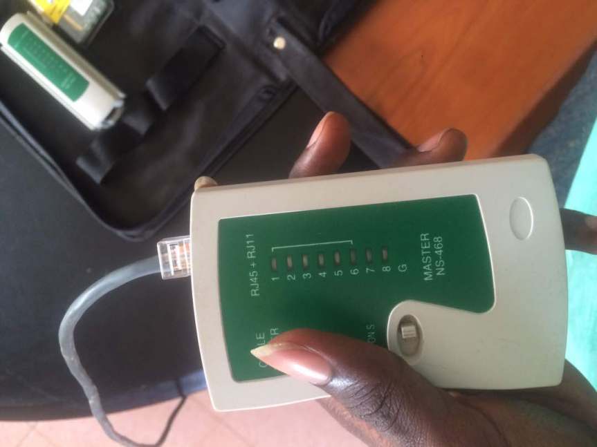
Step 7: Test your cable
You may test with your devices or with this testor that comes with the tool kit
We have a wired network so i connected to the switch
My computer is now Connected

Follow on Quora


Thanxx Sinatra
LikeLike
Good job Sinatra
LikeLike